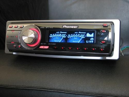

- PIONER DEH P6800MP MANUAL
- PIONER DEH P6800MP FREE
Never feed power to other equipment by cutting.This will damage the lead insulation and cause a very dangerous short. Don’t pass the yellow lead through a hole into theĮngine compartment to connect to the battery.If the insulation of the wiring melts or gets torn, there is a danger of the wiring short-circuiting to the vehicle body.

Do not route wiring in places that get hot, such as near the heater outlet. Moving parts, such as the gear shift, handbrake and seat rails. Route and secure all wiring so it cannot touch any.To protect the wiring, wrap adhesive tape around them where they lie against metal parts. Secure the wiring with cable clamps or adhesive.
PIONER DEH P6800MP MANUAL
Refer to the owner’s manual for details onĬonnecting the power amp and other units, then make connections correctly. To avoid shorts in the electrical system, be sure toĭisconnect the ≠ battery cable before beginning installation. Before installing it in a recre- ational vehicle, truck, or bus, check the battery voltage. This unit is for vehicles with a 12-volt battery and. Jack for the Wired Remote Control Please see the Instruction Manual for the Wired Remote Control (sold separately).ħ When not connecting a rear speaker lead to a Subwoofer With a 2 speaker system, do not connect anything to the speaker leads that are not connected to speakers. Orange/white To lighting switch terminal.īlue/white To system control terminal of the power amp or Auto-antenna relay control terminal (max. Red To electric terminal controlled by ignition switch (12 V DC) ON/OFF. Yellow To terminal always supplied with power regardless of ignition switch position. PIONER DEH P6800MP FREE
If not, keep the Audio Mute lead free of any connections. Yellow/black If you use an equipment with Mute function, wire this lead to the Audio Mute lead on that equipment. Perform these connections when using the optional amplifier. 8) Cadre Pour retirer le cadre, pivotez le haut et le bas du cadre vers l’extérieur afin de le libérer.Connecting cords with RCA pin plugs (sold separately) Installation en utilisant les trous de vis sur les côtés de l’appareil Vis de fixation 1. XRD7112AN 05.8.4 6:12 PM Installation Montage DIN arrière Fixation de la face avant Si vous n’utilisez pas la fonction de dépose et pose de la face avant, utilisez la vis de fixation fournis et fixez la face avant à l’appareil.
L’angle de l’installation, ne doit pas dépasser 60° provisoirement les appareils entre eux pour vous par rapport à l’horizontale, faute de quoi l’unité ne Sortie pour haut-parleur assurer qu’ils fonctionnent c. Avant d’effectuer l’installation définitive, reliez. 7) 7 Lors de l’utilisation d’un haut-parleur d’extrêmes graves sans l’amplificateur optionnel XRD7112AN 05.8.4 6:12 PM Raccordements des appareils Installation Remarque: Dépose de l’unite (Fig. ON, un signal de commande est sorti par le fil Amplificateur Avant de l’installer dans un véhicule de loisir, un Quand la source de ce produit est positionnée sur batterie de 12 V, avec pôle négatif à la masse. Cet appareil est destiné aux véhicules avec une. T T R R A A T T S S N N O O C XRD7112AN 05.8.4 6:12 PM Raccordements des appareils Raccordements des appareils Remarque: 7 Lorsque l’on ne connecte pas de câble de liaison au haut-parleur d’extrêmes graves (When reattaching the frame, point the side with a groove downwards 8) Frame To remove the frame, extend top and bottom of the frame outwards in order to unlock it. Installation using the screw holes on the side of the unit Fixing screw 1. XRD7112AN 05.8.4 6:12 PM Installation DIN Rear-mount Fixing the front panel If you do not operate the removing and attaching the front panel function, use the supplied fixing screw to fix the front panel to this unit. 4) Antenna jack Subwoofer output 15 cm (5-7/8 in.) nections are correct and the system works (Fig. If installation angle exceeds 60° from horizontal, porarily connect the wiring to confirm that the con- the unit might not give its optimum performance. Before making a final installation of the unit, tem. 7) 7 When using a Subwoofer without using the optional amplifier XRD7112AN 05.8.4 6:12 PM Connecting the Units Installation Note: Removing the unit (Fig. 
Before installing it in a recre- this system, be sure not to connect the blue/white (sold separately) ational vehicle, truck, or bus, check the battery lead to the amp’s power terminal. When an external power amp is being used with Power amp negative grounding.T T R R A A T T MANUEL D’INSTALLATION S S N N O O C XRD7112AN 05.8.4 6:12 PM Connecting the Units Note: 7 When not connecting a rear speaker lead to a Subwoofer


 0 kommentar(er)
